Alternator Charging System Wiring Diagrams Body of Knowledge
Starting system circuit diagram https://youtu.be/iwu5ArpfouU

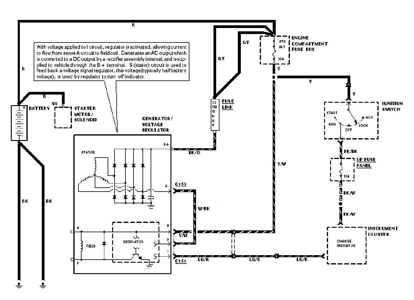
wiring diagram alternator voltage regulator
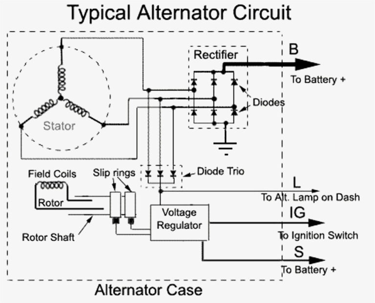
B terminal: Main alternator output terminal (connected to the battery) F terminal: Full-field bypass for regulator Cooling is essential to an alternator's efficiency. It's easy to spot an older unit by the external fan blades found on the rotor shaft behind the pulley. Modern alternators have cooling fans inside the aluminum housing.

How does an Alternator Work?
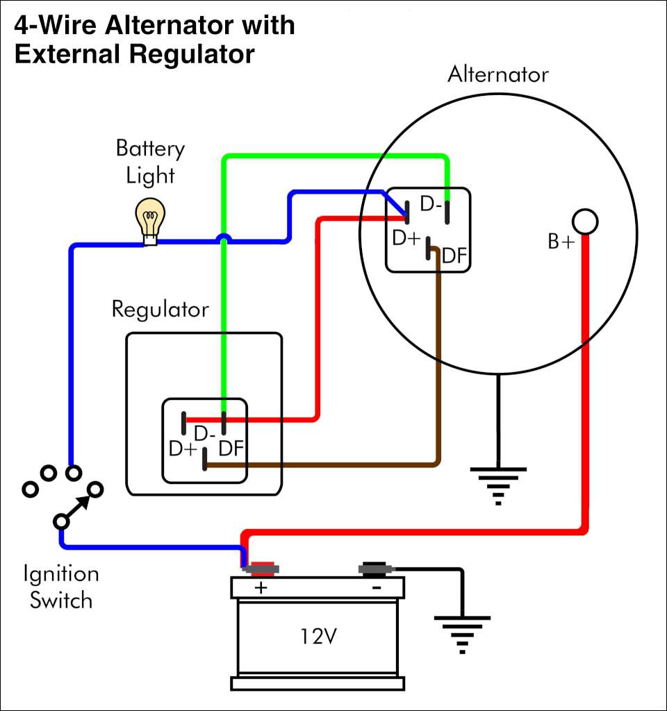
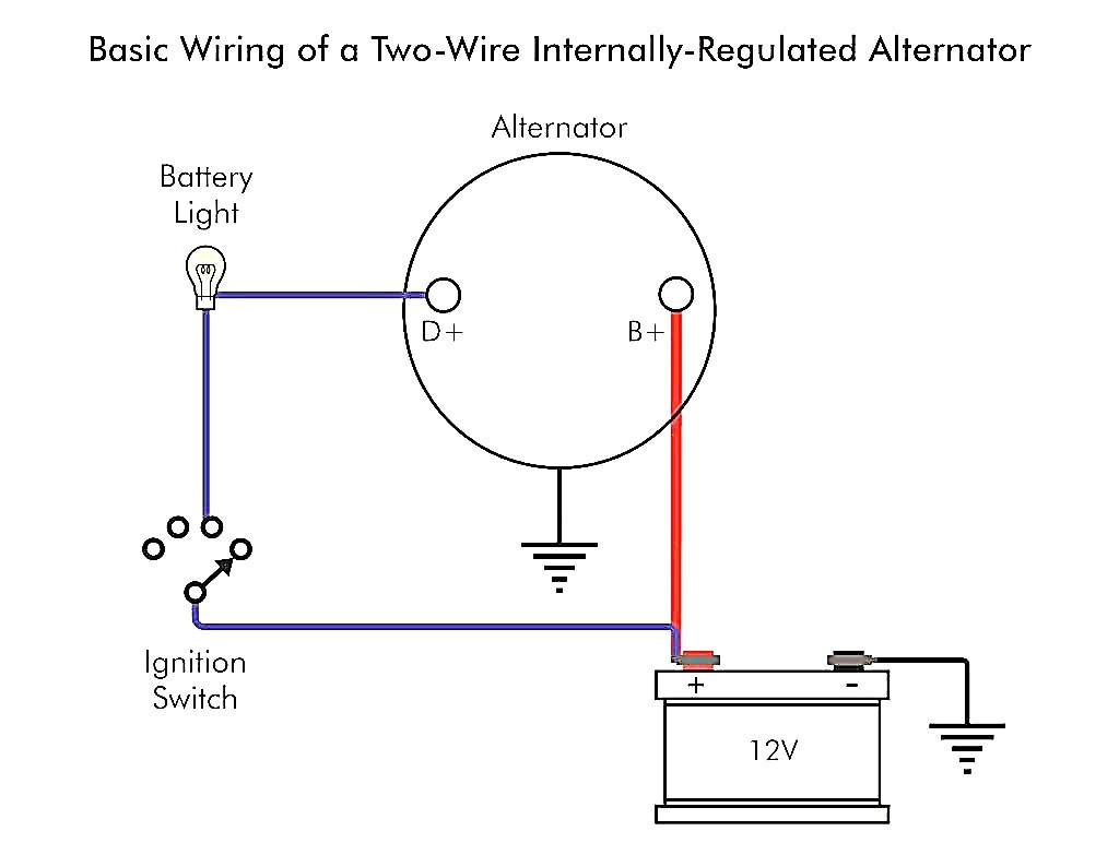
Published on: January 26, 2023 7 min read Contents This article will show you how to wire the exciter wire on an alternator. The exciter wire, which turns the voltage regulator on and is essential for starting your car, is required to generate the required voltage for the alternator to function.
Alternator Circuit Diagram Headcontrolsystem
The alternator voltage regulator circuit is a device that regulates the output of the alternator in a vehicle. It ensures that the correct amount of power is being generated by the alternator and that the battery is receiving the correct amount of charge.

Delco Alternator Wiring Diagram Free Wiring Diagram
Need Help? Ask a mechanic online, 24 hours a day here: https://tinyurl.com/24-7-mechanicIn this video we'll talk about a 3 wire alternator wiring diagram, ho.

Wiring 3 Wire Alternator In Single Wire Alternator Diagram Car
Automotive alternator schematic diagram As the sheave (most people call it a pulley) is rotated by a belt connected to the automobile engine's crankshaft, a magnet is spun past a stationary set of three-phase windings (called the stator), usually connected in a Y configuration.

12 Volt Alternator Wiring Schematic Free Wiring Diagram
Fig. 1: Portion of an alternator stator. The magnetic core of the Stator is built-up of special steel stampings insulated from each other with paper, varnish or oxide coating. These laminations are in the form of complete rings for smaller machines and in segments for larger machines. The laminated construction of the cote minimizes the iron.

Delco 3 Wire Alternator Wiring Diagram Free Wiring Diagram
Circulation Vent Mounting Ear Alternator Overview The alternator contains: A rotating field winding called the rotor. A stationary induction winding called the stator. A diode assembly called the rectifier bridge. A control device called the voltage regulator. Two internal fans to promote air circulation.
Troubleshooting An Alternator Warning Light BMW Car Club of America
Basic Alternator Wiring Diagram. An alternator is an important component in a vehicle's electrical system. It generates electrical power to charge the battery and provide power to the electrical accessories while the engine is running. Understanding the basic alternator wiring diagram is essential for troubleshooting and performing repairs on.

10+ Basic Car Alternator Wiring Diagram Car Diagram (With images
1. What Is An Alternator For? 2. How Does An Alternator Work? 3. Alternator Wire Overview 4. Wire Alternator Wiring Diagram: What Wires Go Where? 5. What Are The 4 Wires On An Alternator 6. What Are The 4 Terminals On An Alternator? 7. How To Wire An Alternator To Charge A Battery? 8. FAQs 9. Final Thoughts What Is An Alternator For?
Si Alternator Wiring Diagram Wiring Diagram Alternator To Battery
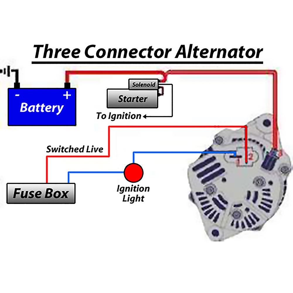
The 3 wire alternator wiring diagram has three electrical connections, as its name suggests. The large connector that connects to the battery is the first. The primary current flow charges the battery and drives the car when the engine is running. There are two smaller terminals on the top of the alternator, typically spade terminals.
Alternator Circuit Explained Jan 19, 2020 · to test a diode in a
Diagram of an Alternator Circuit. Easy to read and follow. Wiring diagrams show the wiring, connectors, and other system related information. They're like road maps for the wiring routed throughout a vehicle.
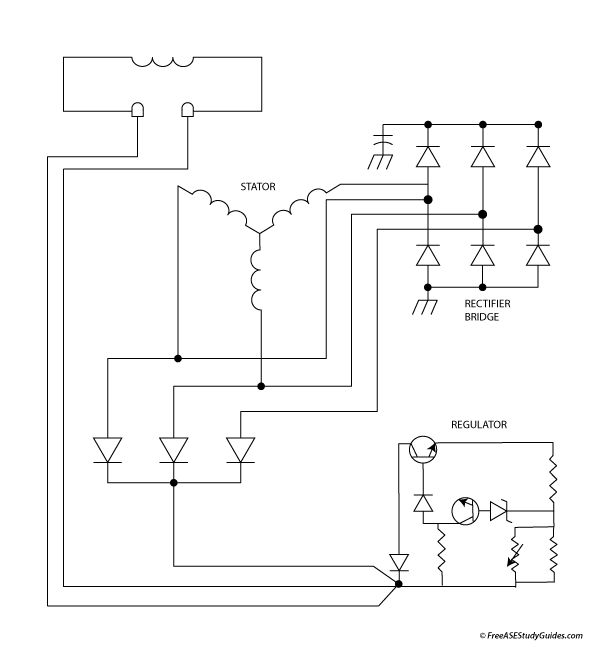
Diagram of an Alternator
Overall, the Bosch alternator regulator circuit diagram is an integral part of any modern car's electrical system, allowing it to get the most out of its alternator and providing accurate and consistent power output. With a little knowledge of electrical principles and a basic understanding of the Bosch alternator regulator circuit diagram.

CHARGING SYSTEM ALTERNATOR Lamp Switch, Voltage Regulator, Diodes, Free
What is alternator function ?Alternator will produce electricity for vehicle needs. This component is very important because it is the only one who serve ele.

Cummins Alternator Wiring Diagram
The 4 simple car voltage current regulator circuits explained below is created as a immediate alternative to any standard regulator and, although developed principally for a dynamo it will function equally effectively with an alternator.

Delco Alternator Wiring Diagram Free Wiring Diagram
An alternator wiring diagram will help you get the basic know-how of the circuit and how the components are linked together in a circuit. So, without further ado, let's dive in. Do you want to know more about what is alternator wiring diagram and how to make your own alternator wiring diagram?